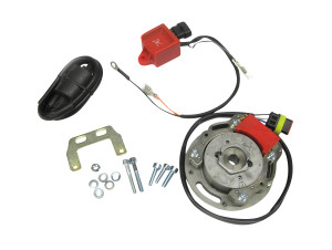
INSTALLATION MANUAL: HPI UNIVERSAL IGNITION - ANALOGUE 1 CYLINDER 2 STROKE
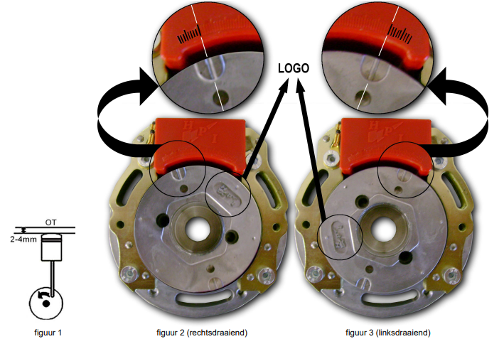
1. Set the piston at 2 to 4 mm before its dead centre. (OT) → see figure 1
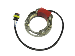
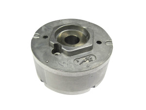
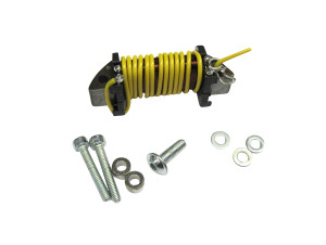
2. Fit the rotor and stator so that both marks correspond.
- for clockwise rotation: 2nd large dash from the left → see Figure 2
- for counterclockwise rotation: 2nd large dash from the right → see Figure 3
Please also note the position of the HPI Logo on the rotor. Do not tighten the screws yet.
3. Make sure that the piston is in the right position and the marks correspond. Adjust if necessary by turning the base plate of the stator.
4. Securely screw down the base plate.
5. Connections:
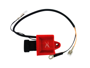
- The 3 pole connector of the stator to the 3 pole connector of the CDI.
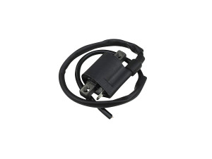
- The orange cable to the HT coil.
- The HT coil should be attached to the frame for ground together with the black cable.
- The black/white cable to the on/off switch.
- The optional yellow and yellow/blue cables are used to select a curve;
- cables unplugged → curve 1
- cables connected → curve 2
NOTES:
- To gain power, you can try adjusting the 2 to 4 mm setting slightly.
- HPI can provide a switch to put between the optional yellow and yellow/blue cables, which makes curve selection very easy.
- The optional yellow and yellow/blue cables must never come into contact with the frame or the ground !!!


